
General
Absolutely! While we do sometimes operate the microscopes for labs that need data in a hurry (Assisted use), we prefer to teach users how to use the instruments to get the most out of their research. You can find more information on what training looks like by following this link.
The answer really depends on what you are trying to accomplish. Is your sample live or fixed, thick or thin, do you have it labelled with nothing, colored stains, fluorescent dyes, etc? This is why we strongly encourage users to contact us for a project consultation before they start preparing samples.
Sample Prep
Plastic labware is not designed for high resolution imaging. The plastic can vary in thickness and refractive index (how matter bends light) all within the same batch of material. Higher magnification lenses (20x or up) are typically designed to work with #1.5 thickness glass coverslips (0.17um), not plastic.
Because the thickness of 0.17um was factored into the design of the microscope objective by the optical engineer. The number is even stamped on the barrel of most objective lenses (there are a few exceptions to this rule). For more information on coverslip thickness and how to find the #1.5H thickness required for super resolution, read the PDF entitled: The importance of #1.5 thickness coverslips for Microscopy.
Optical
Numerical Aperture (NA) is “… a critical value that indicates the light acceptance angle, which in turn determines the light gathering power, the resolving power, and depth of field of the objective.”(1) As light passes through a sample, the information describing the highest resolution information in the sample is diffracted at a very wide angle. Low magnification lenses typically have low NAs, meaning that they cannot capture the highest resolution information. To capture the widely diffracted information, high NA lenses move the front surface of the lens closer to the sample (increases the light acceptance angle). Dry lenses can only have NAs of up to 1.0. By using specially formulated oil and oil lenses, NAs of up to 1.4 can be achieved. There are a few microscope objective lenses with NA>1.40, but the cost goes up very rapidly for every 0.01 increase in NA.
Web tutorials that explain NA in more detail:
- Numerical Aperture and Image Resolution - http://micro.magnet.fsu.edu/primer/java/imageformation/airyna/index.html
- Numerical Aperture Light Cones - http://micro.magnet.fsu.edu/primer/java/nuaperture/index.html
- Immersion Oil and Refractive Index - http://micro.magnet.fsu.edu/primer/java/microscopy/immersion/index.html
References: 1) http://micro.magnet.fsu.edu/primer/anatomy/specifications.html
You can find this information with each of the microscopes, both in the Resource listing on this website for the specific microscope and posted in the microscope room.
If you are interested, the free working distance of microscope lenses typically changes inversely with the numerical aperture. As the NA gets higher the WD gets smaller. Another way to think of this is that as the magnification of the lens increases (usually the NA gets higher as well) the WD gets smaller. There are some specialty microscope lenses that can escape this physics-based “rule of thumb”, but they tend to be quite expensive. https://www.olympus-ims.com/en/microscope/terms/working_distance/
Confocal
Great question! The confocals that we have are what are called “point scanners”. This means that the image is created by using the laser spot and capturing the fluorescence information from a single spot in an image (essentially each pixel, or more correctly each voxel) at a time. Because the resolution of a camera chip is fixed, it doesn’t give us the flexibility to use different numbers of pixels for each magnification or zoom that a photomultiplier does.
There are confocal microscopes that use a camera, they are called spinning disks (there’s one in Chemistry and another in the Cancer center). Spinning disk confocals can be faster in capturing images than a point scanner and are often used for live cell imaging. The downside of spinning disk confocals is that the pinholes on the disk are not adjustable, so that the only lens on the microscope that is optimally configured to use the disk is typically the 60X objective (every other objective lens is a compromise). Point scanning confocals have an adjustable pinhole, so they can get the best possible image with any lens.
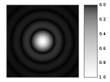
Airy disk (source: https://en.wikipedia.org/wiki/Airy_disk)
When the laser spot interacts with the sample it creates a diffraction spot like the one shown here. The confocal pinhole is set to capture the bright central spot (1 Airy Unit or AU) while ignoring the concentric rings. This captures the most light with the least interfering information (the rings). Newer confocals using low noise detectors and looking at very bright samples can sometimes decrease the size of the pinhole to less than 1 AU and achieve higher optical resolution.
* Sir George Biddell Airy (https://en.wikipedia.org/wiki/George_Biddell_Airy) was the first to describe this diffraction phenomenon, so this unit-less measurement is named in his honour.
Let’s start with why fluorescence using a 40X (NA=1.3) is brighter than a 63X (NA=1.4). There is a physics-based formula (more information) that calculates the brightness of fluorescence for a given microscope lens. Since magnification is in the denominator of the formula, as the magnification increases it actually lowers the calculated brightness value. Using the formula, the brightness value of the 40X is 17.85 and the brightness value for the 63X is 9.68 or about half as bright. For reference a 100X lens would have a brightness value of just 3.84 (21% of the 40X value).
Zoom on a point scanning confocal is pretty much the same as cropping a large image in Photoshop (or similar programs). The field of view is smaller, but the optical resolution is the same. This means that zoom with a 40X objective will be brighter than a 63X with no zoom.